Home | Construction
1 | Construction 2 | Construction
3 | Shopping
List | PC & Configuration | Graphics & Plans
Day 1:
08:00
|
|
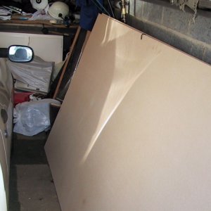
We had already bought
the wood, three sheets of MDF measuring 8 foot by 4 foot each.
WIth the exception of a few small bits we found lying around
the garage, everything was purchased for the construction project.
You can find the 'Shopping List' from the links above.
The plans for the cabinet
were loosely based upon LuSID's
work, but with modifications to the dimensions and control
panel. As we weren't using the same wood thickness as was mentioned
in the plan it really just served as a guide to ensure that the
machine looked correct once assembled. Everything else we kind
of made up as we went along. |
|
|
|
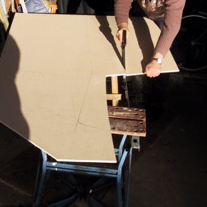
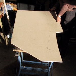
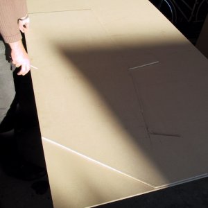
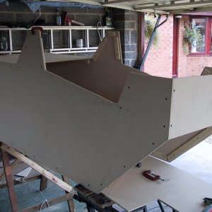
Due to bad weather
during the first part of construction we had no power,
so we began by hand sawing the shape |
|
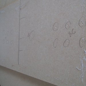
| Careful measurements,
and some rough pencil sketches on the wood served as the
guides |
|
|
|
|
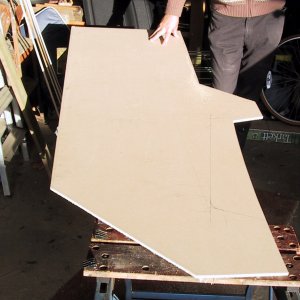
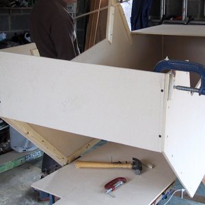
| Rather than LuSID's
huge control panel, we wanted something a bit more subtle.
We also decided to angle the base of the control panel
back in to make the base of the cabinet narrower. This
looked better and didn't take up quite as much room as
the original plans showed. |
|
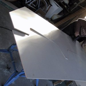
Of
course you need two sides - so simply lay the first side
on a new piece of MDF and draw carefully round it. At this
point without the power tools we couldn't quite cut the
screen edge correctly as it was tricky to get the handsaw
in, and needed a curve to the top marquee unit.
Note
in the pictures above, you're looking at the cabinet
upside down - the bit sticking out at the base will actually
be at the top of the cabinet
|
|
Day
1: 09:16
|
|
|
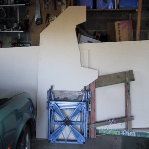
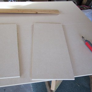
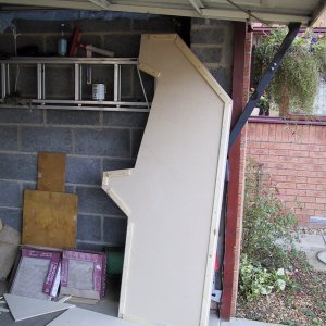
| Just to recap
- this is where we are: One roughly cut side of the cabinet
- and a lot of uncut wood. |
|
The
next thing to do was to finish the first side - mark the
outline on a fresh sheet of MDF, and then cut the second
side out.
This
is much easier with a power saw (the power came back).
|
|
Day 1: 09:49
|
|
|
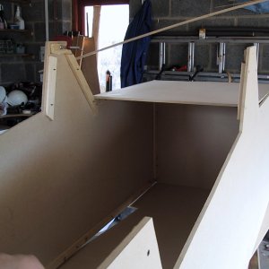
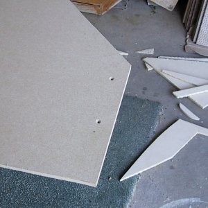
Once
the left and right sides were cut, it was time to cut
the piece for the bottom. We took rough dimensions from
LuSID's plans, modified to whatever the size was of the
edges that we'd already cut.
|
|
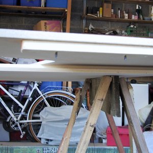
To
go along with the bottom, we needed a top. This would then
make the cabinet free-standing so we could measure and
cut some of the other panel pieces.
|
|
|
|
|
To
hold everything together we used battens added to
the inside of the frame onto which we screwed the
other pieces.
|
|
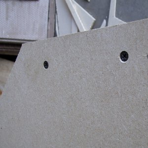
We
screwed them from the outside, countersinking the screw-heads
to allow them to be filled and, ultimately, painted over.
|
|
|
|
|
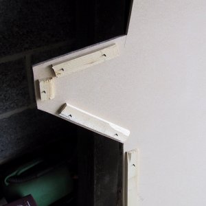
You
can see the two screws in place here
|
|
You
can see the batten screwed onto the outside. Yes, the screws
were too long, but we had already bought 400 of them.
|
|
Day 1: 10:57
|
|
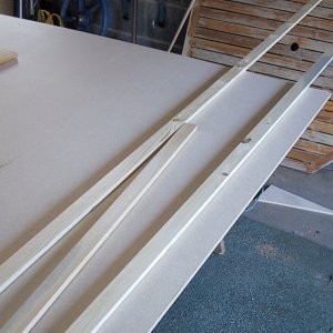
|
You can now
see most of the battens in place on one of the sides.
Two useful tools are resting on the surface - a block
that allowed you to scribe the edge of the frame exactly
9mm
(the
width of the MDF) from the edge - and a small piece
of MDF to check the position before the battens were screwed
in.
In the end
(and much later in construction) for additional stability,
we took all the battens off - glued them - and reassembled
them. If you're sure about what you are doing, you
may as well glue them as you go.
|
|
Here
is the edge piece with all its battens in place.
|
|
|
|
|
A
close-up of the back edge
|
|
And
one of the control panel housing.
|
|
Day 1: 11:39
|
|
|
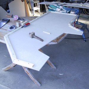
Once
we'd put the battens on both sides, it was possible to
assemble some portions so the cabinet would stand.
|
|
The
cabinet is laying on its back here.
|
|
|
|
|
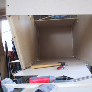
Still
laying on its back, looking at the top and down to the
control panel housing.
|
|
Another
angle - just so you can get the feel for the construction.
|
|
Day 1: 11:50
|
|
|
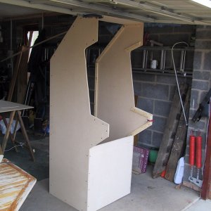
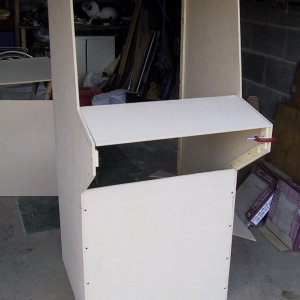
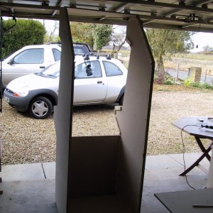
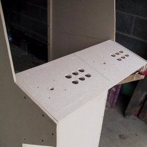
The
first picture of it standing up under its own power!
|
|
The
same view from the back. Not too bad for just over two
hours work
|
|
Day 1: 11:55
|
|
|
It
was now time for the control panel. We cut a piece of
wood to fit the gap and took careful measurements.
|
|
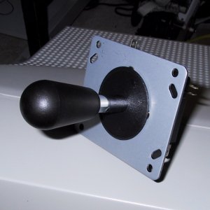
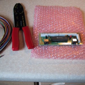
It's
probably a good time to introduce my controls. I chose
to connect the controls to the PC using an I-PAC from Ultimarc.
Whilst I was about it, I got two J-Stiks - a collection
of buttons and a crimping tool.
|
|
|
|
|
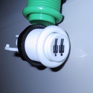
A
couple of the 20 buttons I ordered (which match the inputs
available on the I-PAC).
|
|
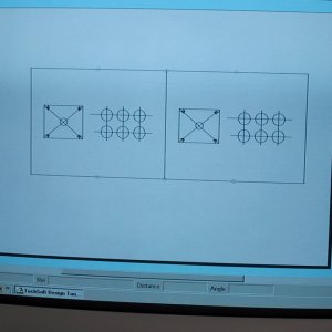
We
programmed the measurements of all the controls, and of
the control panel board into a CAD package which made it
easy to sort out alignment design. Having decided to go
with just the two sticks and six-player buttons on the
main control panel all we had to do was click 'print'
|
|
Day 1: 12:56
|
|
|
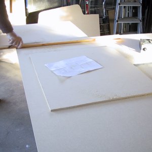
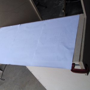
With
the paper in hand, we glued it to the top of the control
panel, making sure to centre it along both axis.
|
|
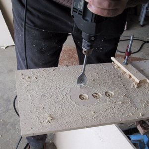
With
the centres of the holes marked out on the CAD package,
we centre-punched each button to enable our big hole-cutting-drill
to get started.
|
|
|
|
|
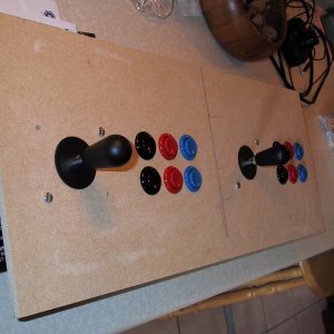
We
drilled each of the twelve button holes from both sides
to make sure that the edges were as smooth as could be.
|
|
A
quick rub over with glass paper and the panel was ready
for wiring.
When
the cabinet is finally decorated there will probably
be some perspex over the control panel to give it some
extra toughness.
|
|
Day 1: 13:29
|
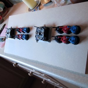
|
|
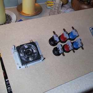
First
the controls were screwed into the panel - taking care
to match the button colours for player one and player
two of course!
|
|
These
were the other things that were going to be needed - wire,
a crimping tool and the I-PAC interface board.
|
|
|
|
|
A
quick turn-over to make sure that everything looked okay.
|
|
And
then installation of the micro-switches in each of the
buttons.
|
|
|
|
|
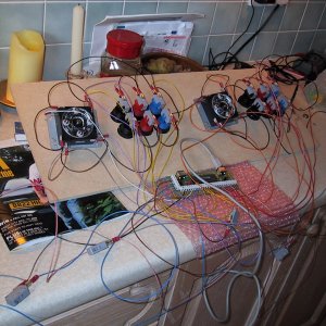
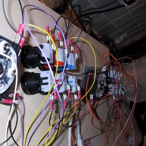
The
wiring was fairly simple - a common line running around
all the controls, then each control individually wired
to the I-PAC. As there were eight more buttons that were
going into the cabinet I just left then trailing for
now whilst I decided where they went (and left plenty
of cable!)
|
|
More
detail of the wired-up controls.
The
gray wire at the bottom of the picture goes to the PC
which was on the floor - I thought it was probably a
good time to give the controls a test. Worked first time
...
|
|
Home | Construction
1 | Construction 2 | Construction
3 | Shopping List | PC & Configuration | Graphics & Plans
|